

-
Products
-
2D Cutting

-
Tube Cutting
-
3D Cutting
-
BLT Intelligent Cutting
-
Industrial Software
-
-
Portfolio
-
-
2D Cutting Head
Tube Cutting Head
Plane Bevel Cutting Head
Structural Steel Cutting Head
-
Popular products
-
- Online Store
- Service & Support
- About BOCHU
- Investors Relations


- Software Download
- Manual
- Video
- Tutorial
Description
- The contour vector is used to showthe cutting direction of the cutting head at differentpoints on the section.
For example, the blue point in the figure below corresponds to a normal vector of contours in the direction of the blue arrow, representing the direction of the cutting head when cutting to this point.
Then the actual cutting to this section will result in a collision between the cutting head and the pipe (as shown in the yellow circle).
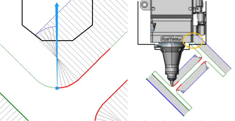
- The original normal vector of contoursof I-beam and concave angle profile pipe at the concave angle often lead to side collision, so the contour vectors need to be modified.
- Modify the contour vector by automatic or manual way until the Interference Detection is passed.
Choose Cutting Head
- Interference Detection is based on the dimensional parameters of the cutting head. For accurate interference results, please use the cutting head configured with correct modeling.
- 2.During Interference detection, there will be a simple schematic diagram to show how the cutting head is involved in interference detection.
- 3. Follow Height is usually set to 1mm without changing.
Interference Detection
- Click <Interference Detection>, the software will detect whether the cutting head will collide with the pipe when cutting to each position of the profile according to the current cutting head size.
- If there is a collision, it will be indicatedwith an error. When cutting to the red marked section, the cutting head will collide with the pipe.
Modify Contour Vector
- If there is interference in the result, the contour vector can be modified automatically and manually so as to adjust the direction of rotation when cutting and avoid collision.
- Click <Self Modified>, TubesTwill detect if there is interference according to the current cutting head dimension, if yes, then the contour vector with interference will be automatically modified. After modification, a prompt will be given: “No Interference” or “There is interference, please check the contour vector”.
- The result of automatic modification may not be symmetrical, but as long as the interference detection is passed, it means that it does not affect the processing.
- If the automatic modification is not successful or the effect is not good, you can modify it manually. Manual modification is mainly achieved by dragging the node. The operations are shown below:

- The contour vector of the H-beam only shows the part that needs to be edited. If you modify it manually, you can click MirrorModify to realize the mirror image modification of the four chamfers.
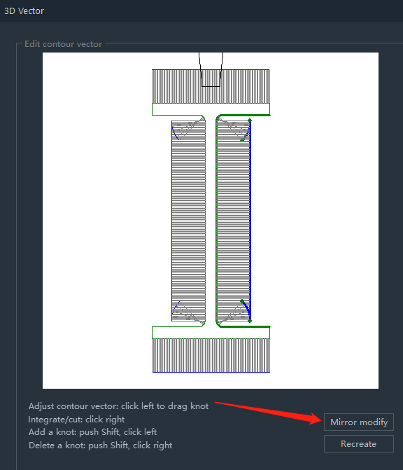
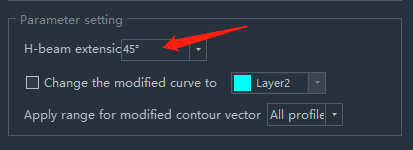
- The H-beam Extension angle is how much the contour vector at the H-beam chamfer shows. Usually 45° is enough, because the cuttingpath at the chamfer of the H-beam is usually also 45° cutoff.
- Click <Recreate> to restore the contour vector to its default state.
- After modification, you must click <OK> to save the modification result.
Modify Layer
Usually, the thickness to-be-cut and the following height at the section with modified contour vectors are not quite the same as the normal cutting when processing. Therefore, it may be necessary to change a layer for the cutting path of modified vector to facilitate the technique debugging of the cutting effect.
Application
- The result of vector modification(possibly including layers) will take effect after clicking<OK>. The effective range is by default all parts of the same section.
- 2. If there is a need for debugging, also it allows you toselect Current Parts or Selected Parts of Same Section (the selected meansthe selected ones in Parts List on the left side).
Description
- The contour vector is used to showthe cutting direction of the cutting head at differentpoints on the section.
For example, the blue point in the figure below corresponds to a normal vector of contours in the direction of the blue arrow, representing the direction of the cutting head when cutting to this point.
Then the actual cutting to this section will result in a collision between the cutting head and the pipe (as shown in the yellow circle).
- The original normal vector of contoursof I-beam and concave angle profile pipe at the concave angle often lead to side collision, so the contour vectors need to be modified.
- Modify the contour vector by automatic or manual way until the Interference Detection is passed.
Choose Cutting Head
- Interference Detection is based on the dimensional parameters of the cutting head. For accurate interference results, please use the cutting head configured with correct modeling.
- 2.During Interference detection, there will be a simple schematic diagram to show how the cutting head is involved in interference detection.
- 3. Follow Height is usually set to 1mm without changing.
Interference Detection
- Click <Interference Detection>, the software will detect whether the cutting head will collide with the pipe when cutting to each position of the profile according to the current cutting head size.
- If there is a collision, it will be indicatedwith an error. When cutting to the red marked section, the cutting head will collide with the pipe.
Modify Contour Vector
- If there is interference in the result, the contour vector can be modified automatically and manually so as to adjust the direction of rotation when cutting and avoid collision.
- Click <Self Modified>, TubesTwill detect if there is interference according to the current cutting head dimension, if yes, then the contour vector with interference will be automatically modified. After modification, a prompt will be given: “No Interference” or “There is interference, please check the contour vector”.
- The result of automatic modification may not be symmetrical, but as long as the interference detection is passed, it means that it does not affect the processing.
- If the automatic modification is not successful or the effect is not good, you can modify it manually. Manual modification is mainly achieved by dragging the node. The operations are shown below:
- The contour vector of the H-beam only shows the part that needs to be edited. If you modify it manually, you can click MirrorModify to realize the mirror image modification of the four chamfers.
- The H-beam Extension angle is how much the contour vector at the H-beam chamfer shows. Usually 45° is enough, because the cuttingpath at the chamfer of the H-beam is usually also 45° cutoff.
- Click <Recreate> to restore the contour vector to its default state.
- After modification, you must click <OK> to save the modification result.
Modify Layer
Usually, the thickness to-be-cut and the following height at the section with modified contour vectors are not quite the same as the normal cutting when processing. Therefore, it may be necessary to change a layer for the cutting path of modified vector to facilitate the technique debugging of the cutting effect.
Application
- The result of vector modification(possibly including layers) will take effect after clicking<OK>. The effective range is by default all parts of the same section.
- 2. If there is a need for debugging, also it allows you toselect Current Parts or Selected Parts of Same Section (the selected meansthe selected ones in Parts List on the left side).
-

Download
-

Contact us
-

Online consultation

