

-
Products
-
2D Cutting

-
Tube Cutting
-
3D Cutting
-
BLT Intelligent Cutting
-
Industrial Software
-
-
Portfolio
-
-
2D Cutting Head
Tube Cutting Head
Plane Bevel Cutting Head
Structural Steel Cutting Head
-
Popular products
-
- Online Store
- Service & Support
- About BOCHU
- Investors Relations


- Software Download
- Manual
- Video
- Tutorial
Brief Description
When there are regular holes(circular, rectangular etc.) which are arrayed on the tubes, it will be much more efficient to apply FlyCut process in TubesT, capable to connect the cutting path in same direction to generate FlyCut path.
Notes: FlyCut process can only be used on FSCUT 5000A, FSCUT 5000B control system, but not for FSCUT3000S control system.
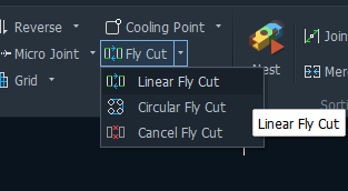
Parameters Definition
- Circular FlyCut
(applied to circular holes)
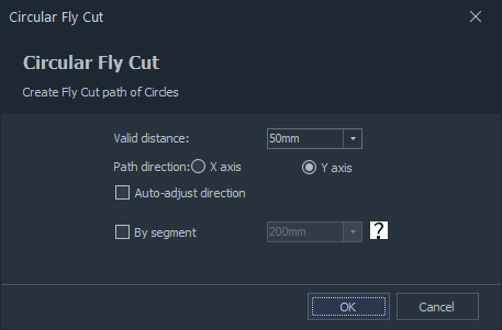
a.Valid Distance
Only when the interval between two holes is within Valid Distance, can FlyCut be applied successfully, so we advise you to set this value larger then actual distance.
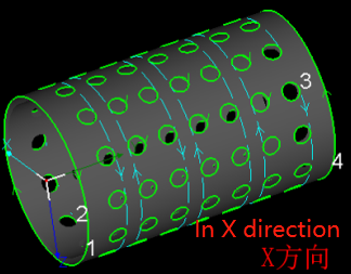
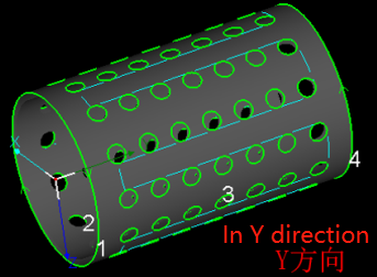
b.Path Direction
You can select FlyCut path direction( X or Y axis) by these two options, the below shows the difference between them.
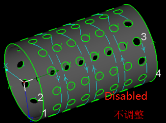
c.Auto-adjust direction
Circular holes with different start position and cutting direction may generate irregular FlyCut lines and also unsmooth trace.

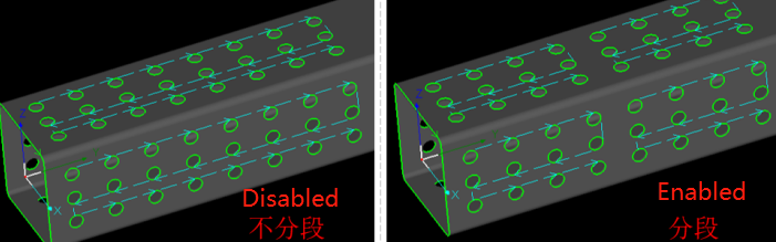
d.By Segment
It is recommended to apply this function to decrease travel path along with Y axis when the holes are on long parts.
e.By Face
For rectangular tubes, it will be much more efficient to apply By Face, the machine will process the holes in different faces respectively to reduce B axis rotation.
- Linear FlyCut
(Applied to rectangular holes, but not rectangular holes with round corners)
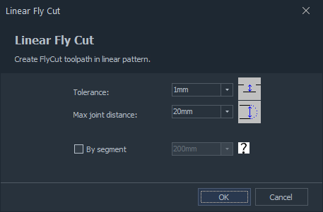
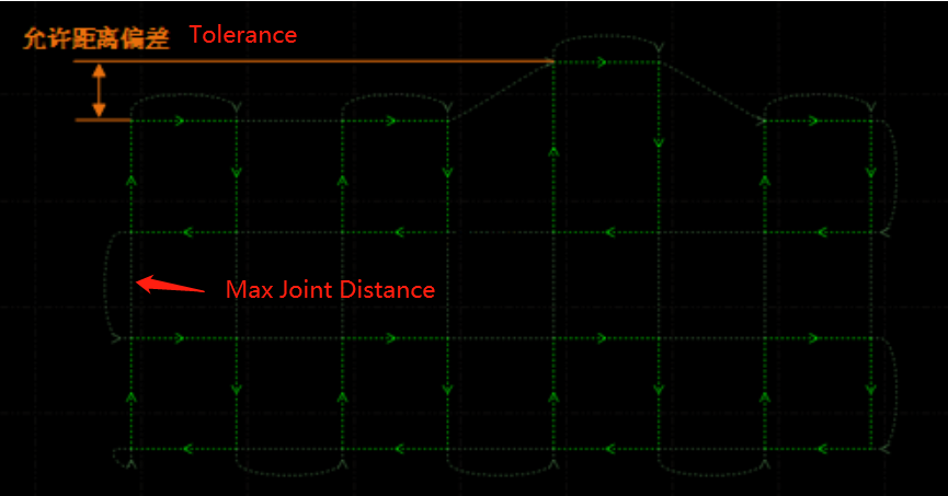
a.Tolerance
If linear deviation in one direction of actual cutting path is in Tolerance preset, these paths will be included into same FlyCut lines, this parameter is set as 20mm by default.
b.Max Joint Distance
- Cancel FlyCut
If you want to adjust FlyCut parameters after it is applied, it is necessary to select the part first and click Cancel FlyCut, then you’re allowed to apply it again with new parameters.
Brief Description
When there are regular holes(circular, rectangular etc.) which are arrayed on the tubes, it will be much more efficient to apply FlyCut process in TubesT, capable to connect the cutting path in same direction to generate FlyCut path.
Notes: FlyCut process can only be used on FSCUT 5000A, FSCUT 5000B control system, but not for FSCUT3000S control system.
Parameters Definition
- Circular FlyCut
(applied to circular holes)
a.Valid Distance
Only when the interval between two holes is within Valid Distance, can FlyCut be applied successfully, so we advise you to set this value larger then actual distance.
b.Path Direction
You can select FlyCut path direction( X or Y axis) by these two options, the below shows the difference between them.
c.Auto-adjust direction
Circular holes with different start position and cutting direction may generate irregular FlyCut lines and also unsmooth trace.
d.By Segment
It is recommended to apply this function to decrease travel path along with Y axis when the holes are on long parts.
e.By Face
For rectangular tubes, it will be much more efficient to apply By Face, the machine will process the holes in different faces respectively to reduce B axis rotation.
- Linear FlyCut
(Applied to rectangular holes, but not rectangular holes with round corners)
a.Tolerance
If linear deviation in one direction of actual cutting path is in Tolerance preset, these paths will be included into same FlyCut lines, this parameter is set as 20mm by default.
b.Max Joint Distance
- Cancel FlyCut
If you want to adjust FlyCut parameters after it is applied, it is necessary to select the part first and click Cancel FlyCut, then you’re allowed to apply it again with new parameters.
-

Download
-

Contact us
-

Online consultation

