-
Products
-
2D Cutting

-
Tube Cutting
-
3D Cutting
-
BLT Intelligent Cutting
-
Industrial Automation
-
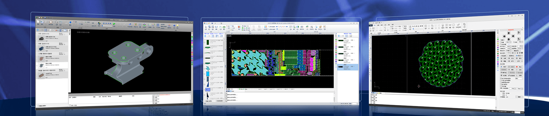
Industrial Software
-
-
Portfolio
-
-
2D Cutting Head
Tube Cutting Head
Plane Bevel Cutting Head
Structural Steel Cutting Head
-
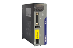
BOCHU High-Speed Servo Drive
-
Popular products
-
- Online Store
- Service & Support
- About BOCHU
- Investors Relations