

-
Products
-
2D Cutting

-
Tube Cutting
-
3D Cutting
-
BLT Intelligent Cutting
-
Industrial Automation
-
Industrial Software
-
-
Portfolio
-
-
2D Cutting Head
Tube Cutting Head
Plane Bevel Cutting Head
Structural Steel Cutting Head
-
BOCHU High-Speed Servo Drive
-
Popular products
-
- Online Store
- Service & Support
- About BOCHU
- Investors Relations


- Software Download
- Manual
- Video
- Tutorial
Description
Create Wrap Feature Part is to add 2D graphics (like DXF files) on the tube as the cutting path, always used for circular, square, rectangular, elipse and round tubes.
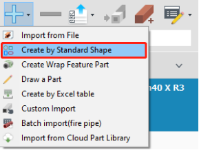
Application
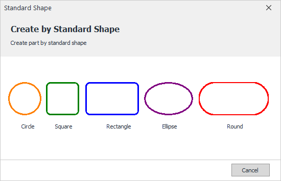
- Select specific tube type, and finish the settings for it(Radius, Width, Length or fillet).
- Open the file for wrapping, set the distance To Left or To Right for DXF files on the tube respectively.

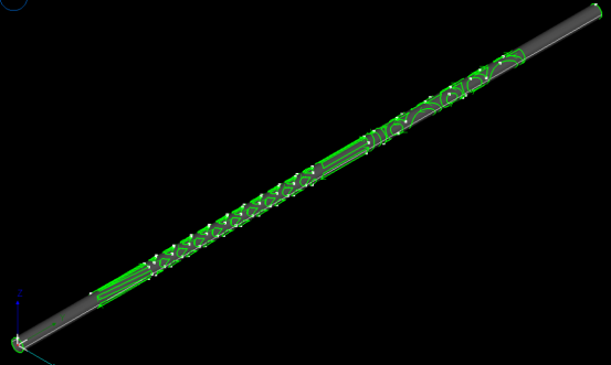
- Click Next to generate a part wrapped by selected DXF file as shown below,
Notes:
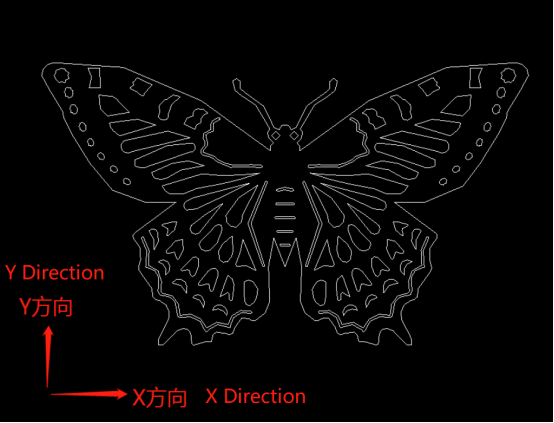
- Graphic Orientation
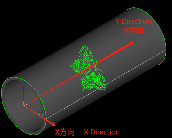
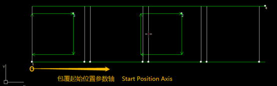
- When creating wrap-featured parts, the Start Position is the distance from the fillet or corner edge to the start point of graphic.
When Start Position is 0, then the left side of the graphic will be placed at the fillet or corner edge.
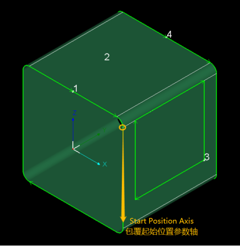
And this is also the start position of 2d surface development, as shown below,
3. If Ignore Fillet is enabled in this interface, then Start Position will not consider the fillets so as to make it convenient to accurately set the position of graphics on the tube.
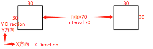
Take a square tube of 50x50mm, fillet radius 5mm as a reference, if you want to add a wrapping drawing which has two square 30x30mm holes with an interval of 70mm,
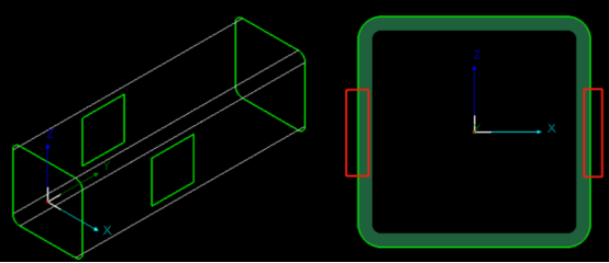
If Ignore Fillet enabled, and set the Start Position as 10 to create symmetric holes on the tube,
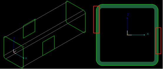
Or you cannot easily make them symmetric because of fillet dimension, as shown below,
Description
Create Wrap Feature Part is to add 2D graphics (like DXF files) on the tube as the cutting path, always used for circular, square, rectangular, elipse and round tubes.
Application
- Select specific tube type, and finish the settings for it(Radius, Width, Length or fillet).
- Open the file for wrapping, set the distance To Left or To Right for DXF files on the tube respectively.
- Click Next to generate a part wrapped by selected DXF file as shown below,
Notes:
- Graphic Orientation
- When creating wrap-featured parts, the Start Position is the distance from the fillet or corner edge to the start point of graphic.
When Start Position is 0, then the left side of the graphic will be placed at the fillet or corner edge.
And this is also the start position of 2d surface development, as shown below,
3. If Ignore Fillet is enabled in this interface, then Start Position will not consider the fillets so as to make it convenient to accurately set the position of graphics on the tube.
Take a square tube of 50x50mm, fillet radius 5mm as a reference, if you want to add a wrapping drawing which has two square 30x30mm holes with an interval of 70mm,
If Ignore Fillet enabled, and set the Start Position as 10 to create symmetric holes on the tube,
Or you cannot easily make them symmetric because of fillet dimension, as shown below,
-

Download
-

Contact us
-

Online consultation

