

-
Products
-
2D Cutting

-
Tube Cutting
-
3D Cutting
-
BLT Intelligent Cutting
-
Industrial Software
-
-
Portfolio
-
-
2D Cutting Head
Tube Cutting Head
Plane Bevel Cutting Head
Structural Steel Cutting Head
-
Popular products
-
- Online Store
- Service & Support
- About BOCHU
- Investors Relations


- Software Download
- Manual
- Video
- Tutorial
Click Draw Part, and you will see the TubeDraw window.
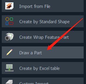
In TubesT, you should draw Main Tube with specific section type and dimension, then use Extrusion Holes, V groove and Extrusion Cut.

If the section you want is not listed, click Smart Draw to draw a 2D draft.

How to use Smart Draw
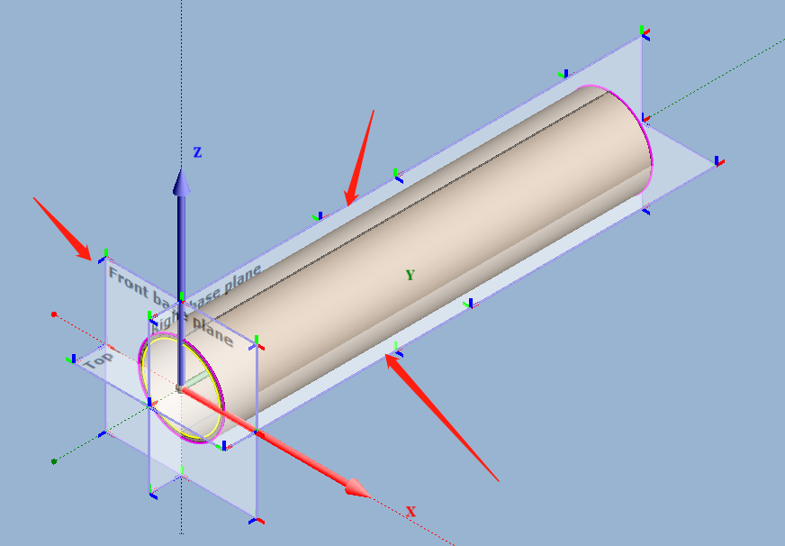
- Draft Plane
- For drawing the section for main tube, no draft plane is needed.
- For Extrusion Hole, select a draft plane or create one.
- Draw Section or Use Template
In Smart Draw, you can edit drawings by Line, Arc, etc., just like in AutoCAD.
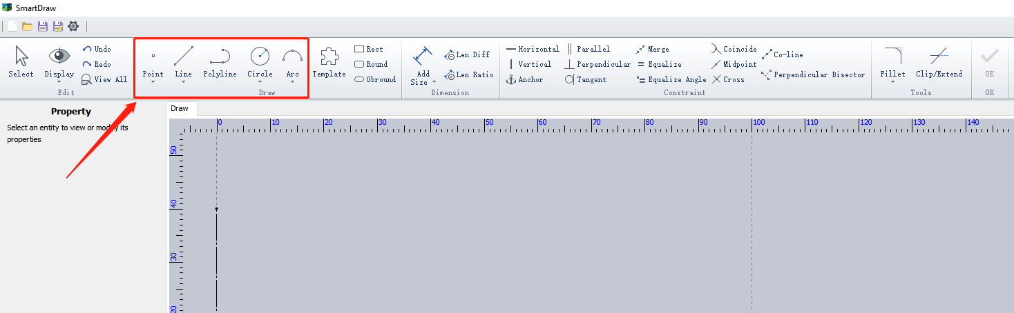
Press Shift when drawing a line, you can make it horizontal, vertical, or 45°.
You can also use a template in SmartDraw. You might need to do some changes on dimensions.
If neither will do for you, add a new template yourself.
- Apply Constraints
The section draft in 2D is determined by Geometry and Dimension Constraints.
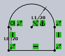
Take the geometry above as an example, its required constraints are shown below:
Geometry Constraints
Horizontal and Vertical lines, Perpendicular Bisector and also Merge the points of lines.
Dimension Constraints
The dimension of lines and graphics, e.g. the vertical line is 20mm long, an arch with a 20mm radius.
Position Constraints
The center of Arch is Fixed.
After all constraints above are set, the shape, dimension and position of the section graphic are determined. Its color will be black after everthing is confirmed. If it is blue, you can modify it.
- Draft Finished
If no content in SmartDraw, the OK button is grey and unailable.
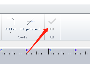
After you finish drawing a draft, you can save it as the section type by clicking OK.
Click the Close button, and your draft will not be saved and you will go back to the TubeDraw window.
![]()
- Draft Modification
Click OK after you finish the section drawing, and return to TubeDraw window to modify the dimension.
For example, you have finished a rectangle section as the Main Tube like this one,
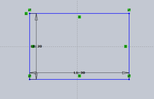
You can see the preview of the tube with its section size on the left bottom of the main interface. You can edit the parameters there.
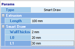
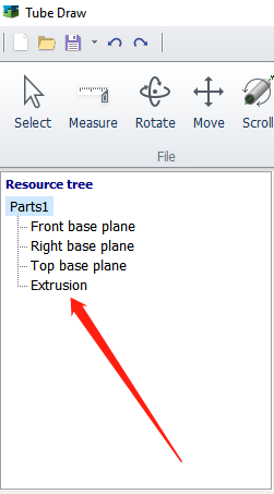
If the section is for Extrusion Holes, you can also click the draft listed in the Resource Tree to modify it in SmartDraw if needed.
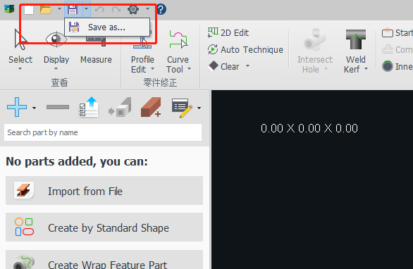
- Save As
You can click New, Open, Save and Save As.
You can save the draft edited as a file in MZB format, which can be used for a template or edit it later.
- Tips
- – For Main Tube: The draft can be open or closed, but but it is required to have only one sequentially connected polyline with each segment’s endpoints constrained with a “merge” constraint. Otherwise, a message will prompt that “the current sketch cannot be used as a cross-section, please modify”
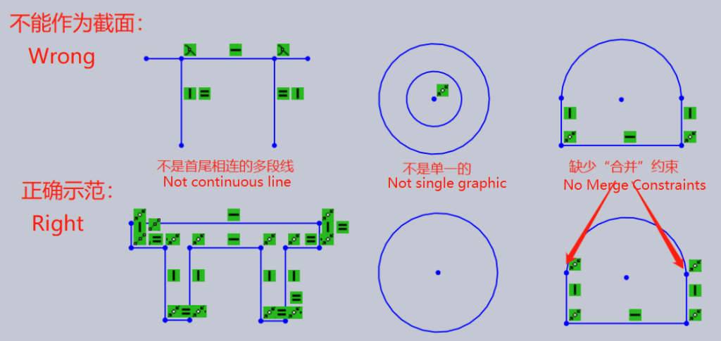
- – For Extrusion Holes: If the drawing is not closed, TubesT automatically connect the endpoints to form a closed shape. If a connected branch has an area of 0, it will not be valid. If multiple shapes intersect, their union will be calculated.
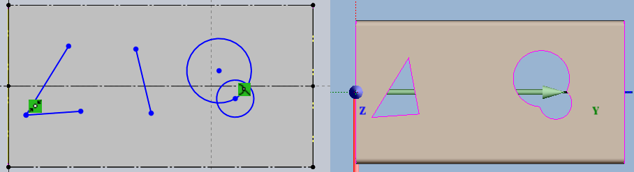
- – You can select multiple graphics by holding Shift. Selecting from left to right: only objects fully enclosed by the selection box will be selected. Selecting from right to left: objects partially enclosed by the selection box will also be selected.
- – Press ESC or click Select on the upper left to quit the current command.
- – Select specific graphics and right click to execute the copy and paste commands.
If you have more questions about SmartDraw, contact tubest@fscut.com or join CAD/CAM discussion group on Whatsapp.

Click Draw Part, and you will see the TubeDraw window.
In TubesT, you should draw Main Tube with specific section type and dimension, then use Extrusion Holes, V groove and Extrusion Cut.
If the section you want is not listed, click Smart Draw to draw a 2D draft.
How to use Smart Draw
- Draft Plane
- For drawing the section for main tube, no draft plane is needed.
- For Extrusion Hole, select a draft plane or create one.
- Draw Section or Use Template
In Smart Draw, you can edit drawings by Line, Arc, etc., just like in AutoCAD.
Press Shift when drawing a line, you can make it horizontal, vertical, or 45°.
You can also use a template in SmartDraw. You might need to do some changes on dimensions.
If neither will do for you, add a new template yourself.
- Apply Constraints
The section draft in 2D is determined by Geometry and Dimension Constraints.
Take the geometry above as an example, its required constraints are shown below:
Geometry Constraints
Horizontal and Vertical lines, Perpendicular Bisector and also Merge the points of lines.
Dimension Constraints
The dimension of lines and graphics, e.g. the vertical line is 20mm long, an arch with a 20mm radius.
Position Constraints
The center of Arch is Fixed.
After all constraints above are set, the shape, dimension and position of the section graphic are determined. Its color will be black after everthing is confirmed. If it is blue, you can modify it.
- Draft Finished
If no content in SmartDraw, the OK button is grey and unailable.
After you finish drawing a draft, you can save it as the section type by clicking OK.
Click the Close button, and your draft will not be saved and you will go back to the TubeDraw window.
![]()
- Draft Modification
Click OK after you finish the section drawing, and return to TubeDraw window to modify the dimension.
For example, you have finished a rectangle section as the Main Tube like this one,
You can see the preview of the tube with its section size on the left bottom of the main interface. You can edit the parameters there.
If the section is for Extrusion Holes, you can also click the draft listed in the Resource Tree to modify it in SmartDraw if needed.
- Save As
You can click New, Open, Save and Save As.
You can save the draft edited as a file in MZB format, which can be used for a template or edit it later.
- Tips
- – For Main Tube: The draft can be open or closed, but but it is required to have only one sequentially connected polyline with each segment’s endpoints constrained with a “merge” constraint. Otherwise, a message will prompt that “the current sketch cannot be used as a cross-section, please modify”
- – For Extrusion Holes: If the drawing is not closed, TubesT automatically connect the endpoints to form a closed shape. If a connected branch has an area of 0, it will not be valid. If multiple shapes intersect, their union will be calculated.
- – You can select multiple graphics by holding Shift. Selecting from left to right: only objects fully enclosed by the selection box will be selected. Selecting from right to left: objects partially enclosed by the selection box will also be selected.
- – Press ESC or click Select on the upper left to quit the current command.
- – Select specific graphics and right click to execute the copy and paste commands.
If you have more questions about SmartDraw, contact tubest@fscut.com or join CAD/CAM discussion group on Whatsapp.
-

Download
-

Contact us
-

Online consultation

